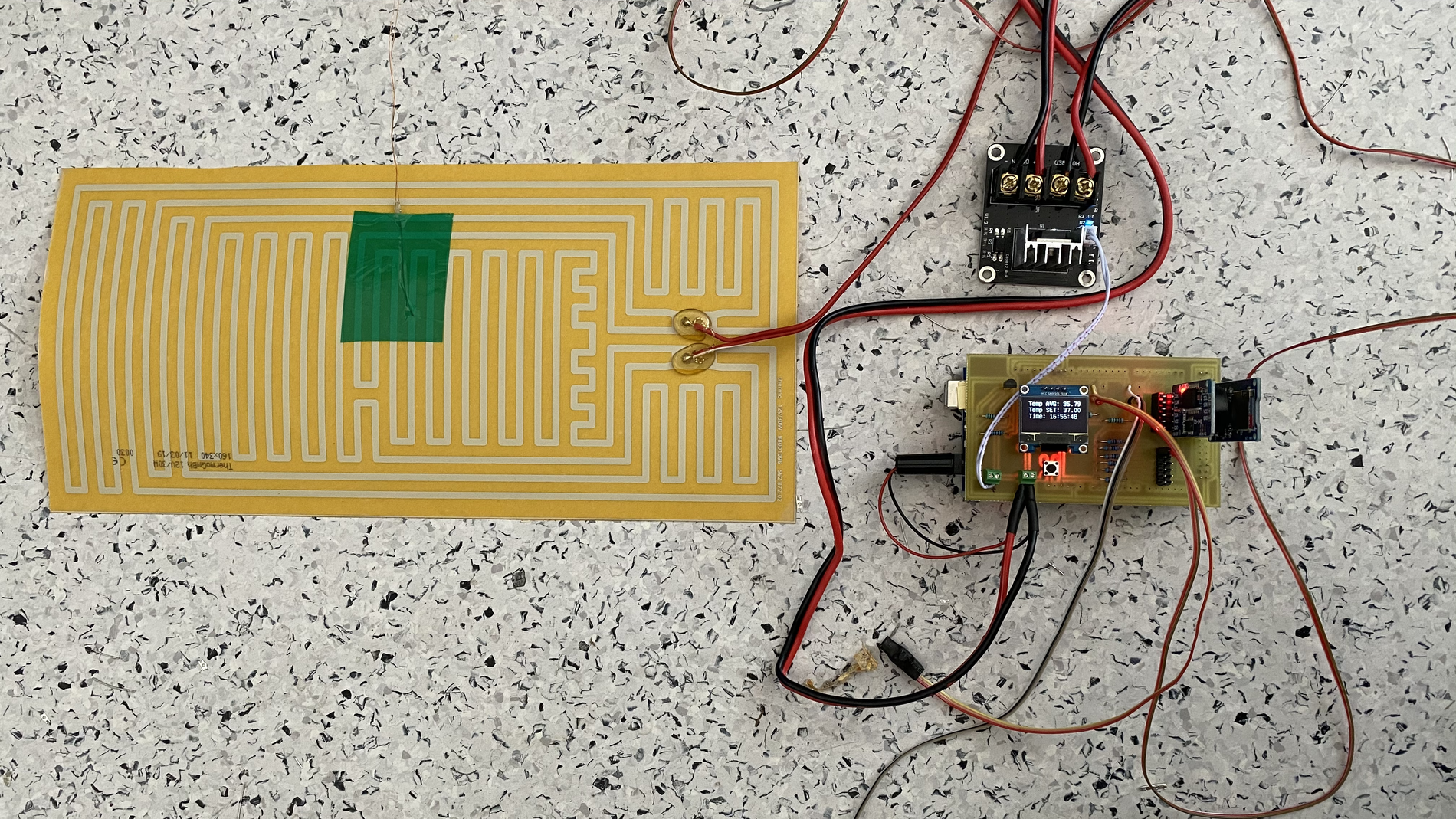
Projekt regulace teploty vyhřívané fólie vstoupil do druhé fáze, ve které se základní regulační obvod realizovaný pomocí drátových propojek nahradil PCB deskou.
V původním projektu byl obvod tvořen drátovými propojkami a to sebou přinášelo komplikace ve stabilitě obvodu. Proto byla navržena PCB deska, která celkovou konstrukci celého obvodu zjednodušila a její funkcionalita je bezpečnější. Navíc byla navržena tak, aby tvořila přídavné pole (shield) pro Arduino mega 2560.
Návrh obvodu
Veškerý návrh obvodu pro zapojení vyhřívané fólie byl realizován v CAD programu EAGLE.
.png)
Pro rychlý vývoj byly použity komponenty:
- Modul pro SD kartu, na kterou se ukládají záznamy o teplotě.
- RTC modul pro reálný čas.
- OLED display, který nahradil display NOKIA 3310. Ten byl absolutně nespolehlivý a vždy se po čase vypnul.
- Tlačítka (S1, S2) pro nastavení teploty a jedno pro reset (S3).
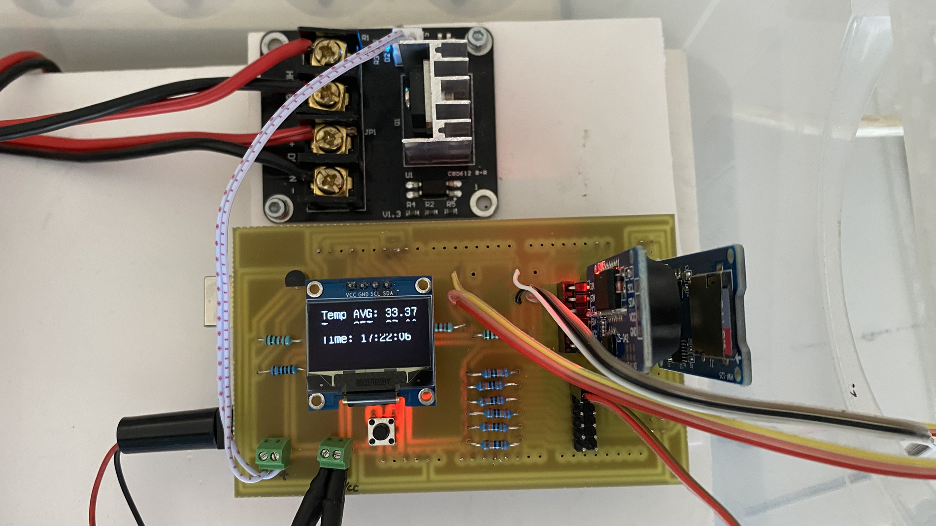
- Tranzistor BC337 do obvodu k zesilovači pro spínání MOSFETu, který je externě připojen ke svorce HOT BED Control In.
- Svorka pro připojení napájení jak desky.
- Sada pinů pro připojení teplotních čidel. Nyní jich lze připojit až 6. Jedná se o čidla dodávaná od společnosti MOUSER. Vyznačující se velmi rychlou reakční dobou a jejich rozměr je řádově 0.81mm. Přesnost je 0,1 stupně C.
- Rezistory 100kΩ, 10kΩ, 1kΩ.
- Řídící deskou je Arduino Mega 2560. U této desky se musí dát pozor na verzi, protože nemusí sedět zejména piny pro SCL a SDA, kterým se připojuje OLED display. Některé verze tto piny nemají dostupné ve dvou místech a musí se následně jediný pár rozdělit.
- Napájení celého obvodu, fólie a obvodu pro regulaci MOSFET je zajištěno zdrojem s několika výstupy 12V.
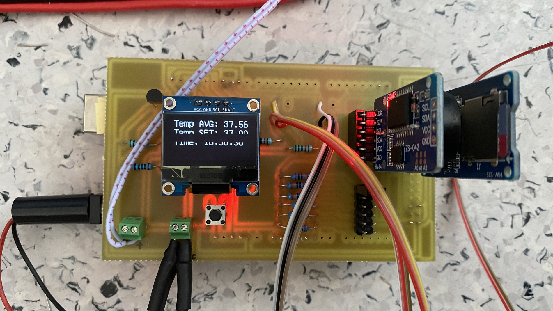
Návrh PCB
PCB byl realizován na jednovrstvou cuprex desku.
.png)
Díky konstrukci jako přídavného pole do Arduino mega je obvod velmi stabilní a tvoří kompaktní celek.
Programování
Programový kód byl použit stejný jako v první verzi akorát byl rozšířen a průměrování hodnot z dalších čidel. Záleží kolik čidel se používá. Využívá se algoritmu tzv. Kalmanova filtru, který zajišŤuje optimalizaci PID regulace.
#include <PID_v1.h>
#include "U8glib.h"
//#include <EEPROM.h>
#include <EEPROMex.h>
#include <PID_AutoTune_v0.h>
#include <DS3231.h>
#include <SPI.h>
#include <SD.h>

// Pins for display
#define RST 8
#define CE 7
#define DC 6
#define DIN 5
#define CLK 4

double Temp;

// Pin for buttons
int buttonPinI = 10;
int buttonPinD = 11;
double readingBtnI=0.1;
double readingBtnD=0.1;
int maxTempBed = 38;                             // Maximum temperature on heat bed

#define VCC 5                                            // Supply voltage
#define SAMPLETIME 100                         // how long between pid/sampling
#define outputPin 9                                     // Analog output pin for MOSFET
#define TEMPERATURENOMINAL 25         // nominal teperature from datasheet thermistor

#define MEDIAN_COUNT 10
#define MEDIAN_DELAY 2

float a=1.110318693e-3;
float b=2.372661717e-4;
float c=0.7473992352e-7;

int numSamples=3;                                  // how many samples to take and average

      #define RT0 10000                            // Ω for MOUSER thermistor
      #define B 3921.26                              // K for MOUSER
      #define R 10362                                  // R=10KΩ for MOUSER
      int numSensors=3;
      //byte sensorPins[] = {A0,A1,A2};
      byte sensorPins[] = {A0, A1, A2};

  //
  /*
      #define RT0 100000                         // Ω for HEAT BED thermistor
      #define B 3950                                  // K for HEAT BED
      #define R 100200                              // R=100KΩ for HEAD BED
      int numSensors=3;
      byte sensorPins[] = {A5, A4, A3};     // define pins for thermistors
  */


// SD card
const int chipSelect = 53;
String fileName="logger.csv";

// Define the aggressive and conservative Tuning Parameters
//double aggKp=6, aggKi=0.4, aggKd=1;
//double consKp=1, consKi=0.05, consKd=0.25;
//double aggKp=15, aggKi=0.3, aggKd=0;
//double consKp=15, consKi=0.3, consKd=0;
//double aggKp=2, aggKi=5, aggKd=1;
//double consKp=2, consKi=5, consKd=1;

//double consKp=2,consKi=0.5,consKd=2;
//double consKp=10,consKi=0.8,consKd=3.4;
double consKp=75, consKi=5,consKd=4.3;

// Variables
float RT, VR, ln, TX, T0, VRT, average;
double input, Output, tempAvgIn, setPoint;
double setPointStart = 30.00;

// For tunning
byte ATuneModeRemember=2;
boolean tuning = false; // if want tunning PID
unsigned long  modelTime, serialTime;
double kpmodel=1.5, taup=100, theta[50];
double outputStart=5;
double aTuneStep=20, aTuneNoise=1, aTuneStartValue=40;
unsigned int aTuneLookBack=20;

//----------------------------------------------

PID myPID(&input, &Output, &setPoint, consKp, consKi, consKd, P_ON_M, DIRECT);
PID_ATune aTune(&input, &Output);

// initialization RTC
Time t;
DS3231  rtc(SDA, SCL);

// initialization LCD display
U8GLIB_SSD1306_128X64 u8g(U8G_I2C_OPT_NONE);

void setup() {
  //EEPROM.writeDouble(1, 36);
  if(tuning){
    tuning=false;
    changeAutoTune();
    tuning=true;
  }
  serialTime = 0;
  Serial.begin(9600);

  pinMode(buttonPinI, INPUT);
  pinMode(buttonPinD, INPUT);

  setPoint=EEPROM.readDouble(1);
  if(setPoint==0 || isnan(setPoint)){
    setPoint = setPointStart;
    myPID.Compute();
  }

  myPID.SetMode(AUTOMATIC);
  myPID.SetSampleTime(SAMPLETIME);

  T0 = 25 + 273.15;                   // Temperature T0 from datasheet, conversion from Celsius to kelvin

  pinMode(chipSelect, OUTPUT);
  Initialize_SDcard();
  Initialize_RTC();

}

void draw(void) {
  // graphic commands to redraw the complete screen should be placed here
  u8g.setFont(u8g_font_unifont);
  u8g.setPrintPos(0, 20);
  // call procedure from base class, http://arduino.cc/en/Serial/Print
  u8g.print("Ahoj!");
}

double Thermistor(int RawADC) {
  //Connection 5V - Thermistor - AI - 10k - GND

  /*
  average = 1024 / average - 1;
  average = R / average;

  float steinhart;
  steinhart = average / RT0;                          // (R/Ro)
  steinhart = log(steinhart);                         // ln(R/Ro)
  steinhart /= B;                                     // 1/B * ln(R/Ro)
  steinhart += 1.0 / (TEMPERATURENOMINAL + 273.15);   // + (1/To)
  steinhart = 1.0 / steinhart;                        // Invert
  steinhart -= 273.15;                                // convert to C
  double Temp=steinhart;
  */
  Temp = log(R * ((1024.0 / RawADC - 1)));
  Temp = 1 / (a + (b + (c * Temp * Temp )) * Temp );
  Temp = Temp - 273.15;            // Convert Kelvin to Celcius

  return Temp;
}

void isort(int *a, int n)
{
 for (int i = 1; i < n; i++)
 {
   int j = a[i];
   int k;
   for (k = i - 1; (k >= 0) && (j < a[k]); k--)
   {
     a[k + 1] = a[k];
   }
   a[k + 1] = j;
 }

}

int analogReadMedian(int port)
{
  int values[MEDIAN_COUNT];
  for(int i =0; i < MEDIAN_COUNT; i++)
  {
    values[i] = analogRead(port);
    delay(MEDIAN_DELAY);
  }
  isort(values, MEDIAN_COUNT);
  return values[MEDIAN_COUNT / 2 + 1];
}

double readTemp(byte tempPin, int numSamples) {
  uint8_t i;
  average = 0;
  // take N samples in a row, with a slight delay

  for (i = 0; i < numSamples; i++) {
    //average += analogRead(tempPin);           // ctemem teplotu
    average = analogReadMedian(tempPin);
    delay(10);
  }
  //average /= numSamples;

  double inputT=Thermistor(average);

 Serial.print("Therm:"); Serial.print(tempPin);Serial.print("-");Serial.print(inputT);Serial.print(" / ");

  return inputT;
}

void loop() {
  t=rtc.getTime();
  readingBtnI = digitalRead(buttonPinI);
  readingBtnD = digitalRead(buttonPinD);

  if(readingBtnI == HIGH){
    setPoint=setPoint+0.1;
    EEPROM.writeDouble(1, setPoint);
  }
  if(readingBtnD == HIGH){
    setPoint=setPoint-0.1;
    EEPROM.writeDouble(1, setPoint);
  }


  uint8_t j;
  double inputS=0;
  for(j=0; j<numSensors; j++){
    inputS+=readTemp(sensorPins[j], numSamples);
  }
  input=inputS/numSensors;

/*
  double gap = abs(setPoint-input); //distance away from setpoint
  if(gap<0.4){  //we're close to setpoint, use conservative tuning parameters
     //myPID.SetTunings(consKp, consKi, consKd);
  }else{        //we're far from setpoint, use aggressive tuning parameters
     //myPID.SetTunings(aggKp, aggKi, aggKd);
  }
*/

   if(tuning){
    byte val = (aTune.Runtime());
    if (val!=0){
      tuning = false;
    }

    if(!tuning){ //we're done, set the tuning parameters
      consKp = aTune.GetKp();
      consKi = aTune.GetKi();
      consKd = aTune.GetKd();
      myPID.SetTunings(consKp,consKi,consKd);
      AutoTuneHelper(false);
    }

  }else{
    myPID.Compute();
  }

  if( input<setPoint){
    analogWrite(outputPin, Output);
  }else{
    Output=0;
    analogWrite(outputPin, Output);
  }

  // Actual temperature on Heat Bed
  String tempC=String(input);
  String tempSetC=String(setPoint);

    u8g.firstPage();
  do {
    u8g.setFont(u8g_font_unifont);
    u8g.setPrintPos(5, 10);
    u8g.print("Temp AVG: ");
    u8g.print(tempC);
    u8g.setPrintPos(5, 25);
    u8g.print("Temp SET: ");
    u8g.print(tempSetC);

    u8g.setPrintPos(5, 40);
    u8g.print("Time: ");
    u8g.print(rtc.getTimeStr());

  } while( u8g.nextPage() );

  /*
  Serial.print("Temperature:");
  Serial.print("t");
  Serial.print(input);
  Serial.print("t");
  Serial.print("setPoint:");
  Serial.print("t");
  Serial.print(setPoint);
  Serial.println("");
  Serial.print("t");
  Serial.print("Ctt");
  Serial.print(input + 273.15);          //Conversion to Kelvin
  Serial.print("Ktt");
  Serial.print((input * 1.8) + 32);      //Conversion to Fahrenheit
  Serial.print("F");
  Serial.print("tt A0 ");
  //Serial.print(VRTa);
  Serial.print("tt");
  Serial.print(Output);
  Serial.println("tt");
  */

  //send-receive with processing if it's time
  if(millis()>serialTime){
    SerialReceive();
    SerialSend();
    serialTime+=200;
  }

 if((t.min==0 || t.min==5 || t.min==10 || t.min==15 || t.min==20 || t.min==25 ||  t.min==30 || t.min==35 || t.min==40 || t.min==45 || t.min==50 || t.min==55  ) && t.sec==0){
    Write_SDcard();
    delay(1000);
 }

  delay(SAMPLETIME);

}

void changeAutoTune(){
 if(!tuning){
    //Set the output to the desired starting frequency.
    Output=aTuneStartValue;
    aTune.SetNoiseBand(aTuneNoise);
    aTune.SetOutputStep(aTuneStep);
    aTune.SetLookbackSec((int)aTuneLookBack);
    AutoTuneHelper(true);
    tuning = true;
  }else{ //cancel autotune
    aTune.Cancel();
    tuning = false;
    AutoTuneHelper(false);
  }
}

void AutoTuneHelper(boolean start){
  if(start){
    ATuneModeRemember = myPID.GetMode();
  }else{
    myPID.SetMode(ATuneModeRemember);
  }
}

void SerialSend(){
  Serial.print("setpoint: ");Serial.print(setPoint); Serial.print(" ");
  Serial.print("input: ");Serial.print(input); Serial.print(" ");
  Serial.print("output: ");Serial.print(Output); Serial.print(" ");Serial.println();
  if(tuning){
    Serial.println("tuning mode");
  }else{
    /*
    Serial.print("kp: ");Serial.print(myPID.GetKp());Serial.print(" ");
    Serial.print("ki: ");Serial.print(myPID.GetKi());Serial.print(" ");
    Serial.print("kd: ");Serial.print(myPID.GetKd());Serial.println();
    */
  }
}

void SerialReceive(){
  if(Serial.available()){
   char b = Serial.read();
   Serial.flush();
   if((b=='1' && !tuning) || (b!='1' && tuning)){
    changeAutoTune();
   }
  }
}


// ************** HW ***************
// Init the DS3231 using the hardware interface

void Initialize_RTC()
{
   // Initialize the rtc object
  rtc.begin();

//#### the following lines can be uncommented to set the date and time for the first time###
/*
rtc.setDOW(WEDNESDAY);     // Set Day-of-Week to SUNDAY
rtc.setTime(14, 21, 00);     // Set the time to 12:00:00 (24hr format)
rtc.setDate(23, 6, 2021);   // Set the date to January 1st, 2014
*/
}

void Initialize_SDcard()
{

  delay(3000);
  Serial.println("Initializing SD card...");
  if (!SD.begin(chipSelect)) {
    Serial.println("Initialization failed!");
    return;
  }
  Serial.println("Initialization done.");
  /*
  delay(1000);
  if (SD.exists(fileName.c_str())) {
    Serial.println("Old file deleted ...");
    SD.remove(fileName.c_str());
  }
  */
  delay(1000);
  Serial.println("Create new file...");
  File dataFile = SD.open(fileName.c_str(), FILE_WRITE);
  dataFile.println("Date;Time;Temp;SetPoint");
  dataFile.close();

  delay(5000);
  Serial.println("========START========");

}

void Write_SDcard()
{

  File dataFile = SD.open(fileName.c_str(), FILE_WRITE);

  if (dataFile) {
    dataFile.print(rtc.getDateStr());
    dataFile.print(";");

    dataFile.print(rtc.getTimeStr());
    dataFile.print(";");

    dataFile.print(input);
    dataFile.print(";");

    dataFile.print(setPoint);
    dataFile.print(";");

    dataFile.println();
    dataFile.close(); //Close the file
  }else{
    Serial.println("OOPS!! SD card writing failed");
  }
}
Soubory ke stažení
Soubory EAGLE - zip
Souboru Arduino - zip